
Introduction:
A line following robot is a robot that is designed to follow a high contrast line (usually a black line on a white surface and vice versa). The main idea behind this robot is to detect black line using 2 IR sensors and move the robot accordingly using the L298N motor driver module. The concept of the line follower robot is related to light. We make use of the way light behaves on a black-and-white surface. The black line absorbs all the light whereas the white surface reflects it. These robots use various sensors to detect the line and navigate along it, making real-time adjustments to stay on course. These robots are commonly used in educational settings to teach robotics, electronics, and programming concepts. They are also used in industries to deliver materials from one place to another.
How Does it Function?
Before getting started, let’s first know the functions of a line following robot’s components:
Sensors - Infrared (IR) sensors or light-dependent resistors (LDRs) are commonly used. These sensors detect the difference in reflectivity between the line and the surface. A black line on a white surface reflects less light than the white surface, which the sensors can detect. Here, the IR LED is an emitter, and the IR photodiode is a detector. An IR LED emits the IR light, and the photodiode is sensitive to this IR light. When IR light falls on the photodiode, the output voltages and the resistances will change in proportion to the magnitude of the received IR light.
Microcontroller- An Arduino or similar microcontroller processes the sensor data and makes decisions on how to control the motors. The board is programmable with the Arduino IDE (Integrated Development Environment) platform via a type B USB cable.
Motor Driver - A device like the L298N motor driver module receives signals from the microcontroller and powers the motors accordingly.
Motors - DC motors or stepper motors move the robot forward, and their speed and direction are controlled to steer the robot.
Power supply - Batteries provide the necessary power to the components.
Sounds interesting? Let’s get started!
What you need:
1. A 2wd car chassis (see figure 2)
OR you can simply build the chassis by yourself using a plastic board. Moreover, you can also make a printed circuit board as well.
2. TT gear motors
3. Screws and switch
4. Arduino uno
5. 2 IR sensors
6. L298N motor drivers
7. Double sided tape
8. Black electrical insulation tape
9. 7-12 V dc battery
10. Jumper wires
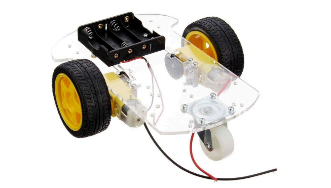
Figure 2: 2wd car kit
Step 1: Assemble the Robot Chassis
Attach the motors to the chassis. Mount the wheels onto the motor shafts. Secure the battery holder to the chassis. Solder wires to gear motors. Use connectors and wires to attach the gear motors onto the car chassis.
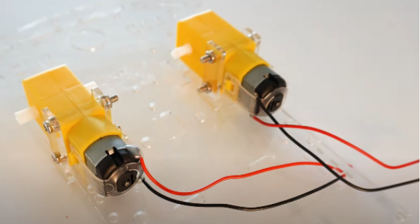
Figure 3: motor drivers
Next, attach L298N motor drivers on the car chassis and then by using double sided tapes place arduino uno on it. Attach two IR sensors in front of the car using a glue gun. Solder battery connector wires to switch and fix it on the car chassis.
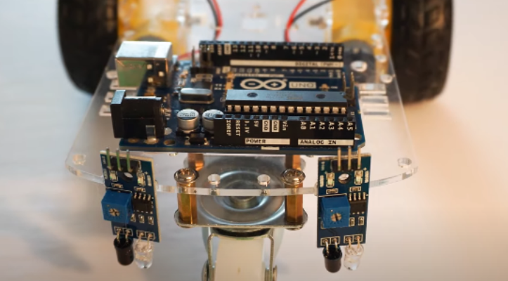
Figure 4: : IR sensors in front of the car
Step 2: Circuit
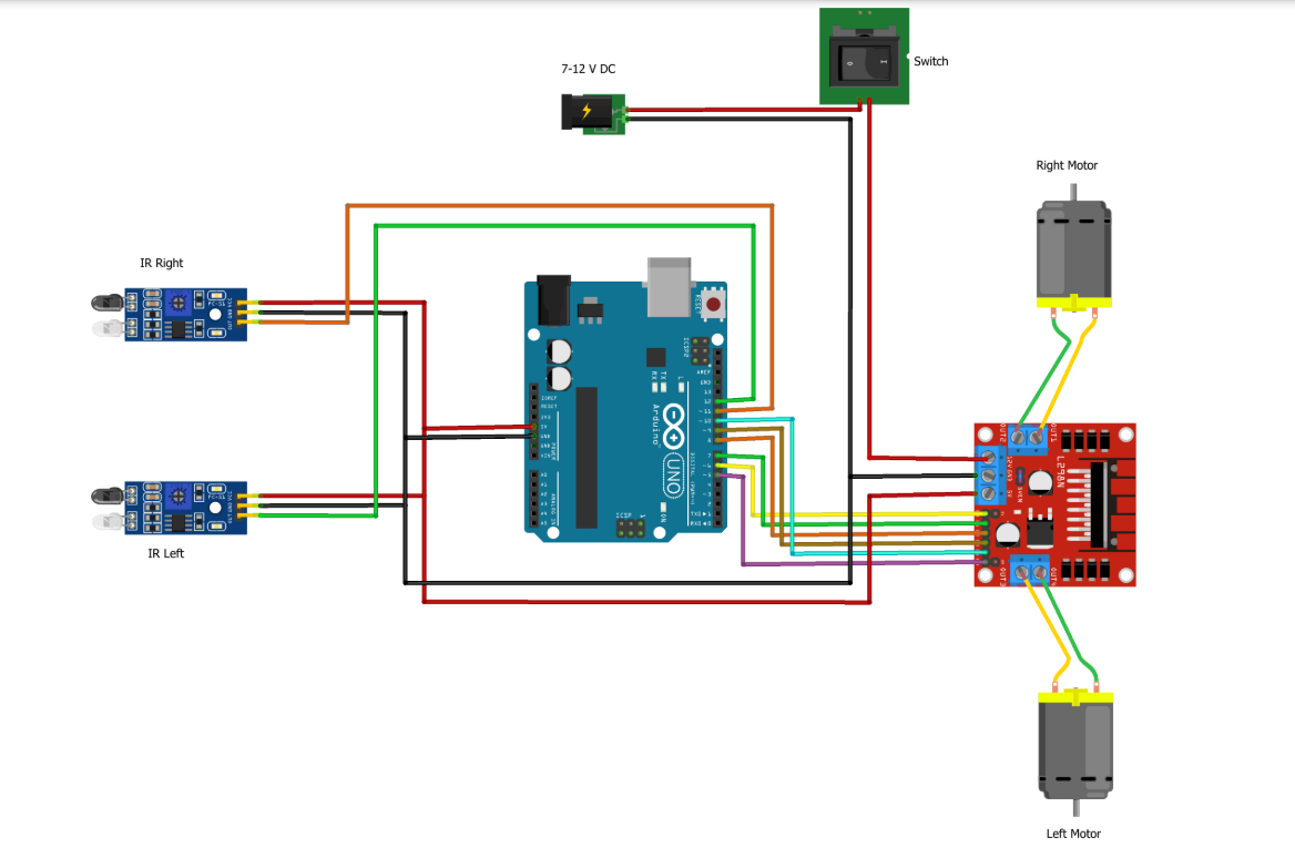
Figure 5: Circuit Diagram
Make the connection as per the circuit diagram. First, connect the left and right motors to the motor driver module.
Next connect L298N motor driver module to Arduino uno pins as per table.
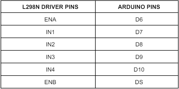
Figure 6: L298N motor driver and Arduino connections
Attach wires to plus 5 volt and ground pins of the motor driver module. Take the +5 volt and ground from L298N motor driver module and connect to two IR sensors. Also provide +5 volt and ground pins to arduino uno. Now, connect right and left IR sensors outpins to D11 and D12 respectively.
Last but not the least connect wires from switch to +5 volt and ground pin of motor driver module and then place battery on car chassis and connect it.
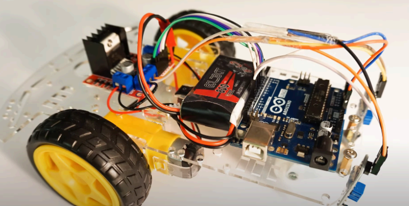
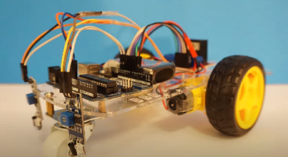
Figure 7: Final look of the robot!
Step 3: Arduino Line Follower Robot Code
The programming part of the line follower robot is very simple and we require only basic Arduino functions. Open the Arduino IDE on your computer. Connect your Arduino to your computer using a USB cable. Write or upload the following code:
Step 4: Adjusting sensitivity of IR sensors
Make a path using black electrical insulation tape ( keep thickness around 4 cm). Place the right IR sensor on black line and adjust the potentiometer so that the led does not glow. Do the same for the left sensor.
Done? Test your robot.
By following these steps, you should have a functional line-following robot. Experiment with different sensor configurations and code adjustments to improve its performance. Check out the video of our robot in the gallery. Stay tuned for getting ideas about more projects like this. Happy building!
Comments